Visionect System Boards
Visionect System Boards are hardware boards created to be the basis of Visionect products and solutions. They have been developed from the ground up to be especially suited for the development of digital signage applications that use various electronic paper screens.
The System Boards come with different types of connectivity options (WiFi, 3G, Ethernet) and can drive various electronic paper sizes. Multiple screens can be driven by a single driver board and multiple driver boards can be tiled together to create very large display surfaces. Finally, the power options enable the creation of products with very long battery life or even that of completely autonomous and self-sustainable outdoor systems that can be indefinitely powered by a solar cell.
Note
Visionect System Boards used to be known as Visionect driver boards - Panda DS (the 9.7”/13.3” version) and Quad (the 32” version).
Visionect 9.7”/13.3” System Board
Visionect 9.7”/13.3” System Board are intended to be used with the 9.7” and 13.3” E Ink® electronic paper displays.
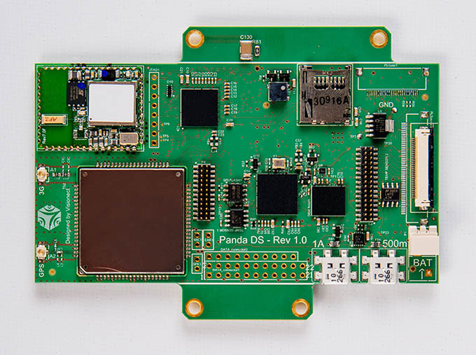
The Visionect 9.7”/13.3” System Board
Display support
The 13.3’’/9.7’’ System Board can drive either the 9.7” or 13.3’’ E Ink® electronic paper display. All hardware and firmware features are the same for both variants with the exception of supported display type.
Setting VCOM
Every electronic paper display comes with a VCOM label. The VCOM setting is unique for each screen and controls the baseline for the white and black colors. Because of that, a wrong setting might reduce image contrast.
You can set the display VCOM using the device configuration pane in Visionect Server or using the command line interface.
Warning
The wrong VCOM setting can lead to unexpected display damage and/or reduce its lifespan!
Communication
Visionect System Boards come with either Wi-Fi and cellular connectivity or Ethernet and cellular connectivity options. Regardless of what connectivity mode you choose, the devices communicate with the server using standard TCP/IP connectivity.
Cellular connectivity
The Visionect 13.3”’/9.7” System Board uses standards-based certified 2G/3G modules with a slot for a Micro SIM card, located on the back side of the board. The configuration of various APN settings (network-dependant) can be done manually. The integrated 2G/3G module supports Quad 2G, while supported 3G bands differ between three 3G module variants and are determined by regional/carrier compatibility. The bands need to be confirmed prior to ordering, so please send your target network/area with your order.
To use 2G/3G connectivity mode, an activated SIM card is necessary, as well as a 3G antenna (connected to 3G connector of the Visionect System Board).
Note
Micro SIM connector: The Micro SIM connector is located on the back side of the Visionect System Board. The front MicroSD connector is currently not supported.
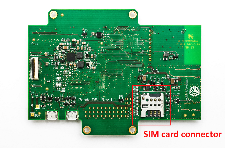
The Micro SIM card connector at the back of a Visionect 9.7”/13.3” System Board
Wi-Fi connectivity
The Visionect 13.3”/9.7” System Board uses standards-based certified IEEE 802.11 B/G/N modules with WPA2-PSK encryption. The modules are configured to use WMM-Power Save features on access points that support the functionality.
The Wi-Fi network quality will critically determine performance and stability. Every device relies on good Wi-Fi connectivity, so a noisy environment with a lot of clients running on low quality access points will cause problems.
The quality and configuration of the Wi-Fi access points also plays an important role when determining battery life and the device autonomy of a device in standby, but still connected. Find out more about power consumption, battery life and optimizations here.
Ethernet connectivity
Standard 10BaseT/100BaseTX Ethernet, Auto negotiation (Full/Half duplex, 10/100 based). IP fragmentation is not supported. Due to space concerns, the Ethernet cable connects via flying-lead by soldering to connection points. The Ethernet module replaces the Wi-Fi module on the Visionect 13.3”/9.7” System Board, as both modules cannot be mounted at the same time.
Power options
The Visionect 13.3”/9.7” System Board can be powered directly, by using a 3.5-4.2V, 2A power supply or a single Lithium-Ion or Lithium-Polymer cell (3.7V-4.2V) with capacity between 1000 mAh and 10000 mAh. The attached battery is connected to the BAT connector, which is further connected to the LIPO charging circuit.
Warning
The Visionect 13.3”/9.7” System Board should be connected to the battery or power supply to ensure a stable power supply as well as a protection against spikes.
The System Board also features Micro USB connectors which will charge the connected battery with the help of a built-in charging chip. There are two Micro USB connectors a Board: 1A and 500m. The 1A connector enables charging the battery with higher current, but doesn’t provide serial port connectivity that the 500m connector does. When it comes to charging, the 1A connector has the absolutely priority, given due to the hardware design.
By connecting a 5V solar cell you could run a 9.7”/13.3” System Board forever, as long as you make sure that your energy consumption doesn’t deplete your batteries. The battery levels are displayed in the Management Interface.
Note
Users who want to use the BAT connector for their own power supply (instead of the attached battery) should note that the BAT connector is connected to the charging circuit. Should the voltage fall below 4.2V while also powering the Board by connecting a USB cable, it might start to charge the battery, which could consequently cause damage to your external power supply (power supply dependent).
External buttons
Visionect System Board 9.7”/13.3” Visionect System Boards feature support for external buttons. For use in applications, please check the button push event section. Before use, check the external button extension scheme below.
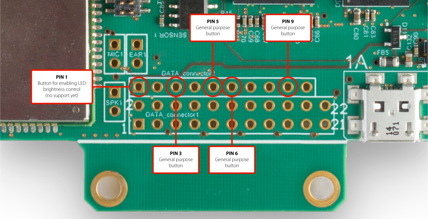
External buttons extension scheme
Extension list
| DATA_Connector pin | Extension board pin | Function (from MCU) | Description |
|---|---|---|---|
| 1 | SCL | I2C SCL | LED PWM controller NCP5623 I2C SCL |
| 2 | SDA | I2C SDA | LED PWM controller NCP5623 I2C SDA |
| 3 | BM_ON | Digital output TTL (1=ON, 0=OFF) | Battery monitor supply control |
| 4 | LDR_ON | Digital output TTL (1=ON, 0=OFF) | LDR supply control |
| 5 | PUEN | Digital output TTL (1=ON, 0=OFF) | LDR supply control |
| 6 | STNDBY_SWITCH | Digital input (5V tolerant) (0=ON, 1=OFF) | Standby switch |
| 7 | UART RX | Serial RX | Text2speech module TX pin |
| 8 | UART TX | Serial TX | Text2speech module RX pin |
| 9 | CAN RX | Can BUS RX | Not supported by FW |
| 10 | CAN TX | Can BUS TX | Not supported by FW |
| 11 | LDR | Analog input (0-3.3V) | LDR resistor divider voltage |
| 12 | BATTERY_MONITOR | Analog input (x0.4125) (0-3.3V) | Battery monitor voltage |
| 13 | HEATER_ON | Digital output TTL (1=ON, 0=OFF) | Heater control (no support yet) |
| 14 | SLEEP_STATUS | Digital output TTL (1=sleep, 0=awake) | vPlatform sleep status |
| 15 | UART RTS | Digital output TTL (0=ON, 1=OFF) | Text2speech module power enable |
| 16 | GPIO4 | GPIO | Not supported by FW |
| 17 | VI_MEAS_ON | Digital output TTL (0=ON, 1=OFF) | V/I measurement supply enable |
| 18 | GPIO6 | GPIO | Not supported by FW |
| 19 | GPIO7 | GPIO | Not supported by FW |
| 20 | AMBILIGHT_OFF | Digital output TTL (0=ON, 1=OFF) | Ambilight supply status |
| 21 | GND | GND | |
| 22 | 3V3 | +3.3V |
| DATA_Connector 2 pin | Extension board pin | Function (from MCU) | Description |
|---|---|---|---|
| 1 | LED button | Digital input (5V tolerant TTL) (1=ON, 0=OFF) | Button for enabling LED brightness control (no support yet) |
| 3 | Button 0 | Digital input (5V tolerant TTL) | General purpose button |
| 5 | Button 1 | Digital input (5V tolerant TTL) | General purpose button |
| 6 | Button 2 | Digital input (5V tolerant TTL) | General purpose button |
| 9 | Button 3 | Digital input (5V tolerant TTL) | General purpose button |
To configure the device, check the configuration section.
Configuring the Visionect 9.7”/13.3” System Board
The Visionect 13.3”/9.7” System Board is configured using the provided Micro USB configuration cable and the Visionect Configurator. You will use the Configurator to configure the network and other device parameters.
You will need to connect the configuration cable to the Micro USB port on the System Board labeled 500m, while connecting the other port to the PC. The USB configuration cable comes with an integrated RS232-USB converter (FTDI) and cannot be replaced with a regular Micro USB cable. Find out more about configuring Visionect products here.
Note
You can order a replacement USB configuration cable by contacting sales@visionect.com.
Note
Mac/OSX users may experience issues with device detection due to issues related to the USB driver. The manufacturer has issued an official update, that should resolve these issues. Download at (http://www.ftdichip.com/Drivers/VCP.htm).
Specification
| Parameter | Specifications | Unit |
|---|---|---|
| Display |
|
|
| Wi-Fi Connectivity | 2.4GHz IEEE 802.11 B/G/N standard, WPA2-PSK support. | |
| Ethernet Connectivity |
|
|
| Cellular connectivity |
|
|
| Battery support |
|
|
| Power supply |
|
|
| Dimensions | Size (H/W): 110 x 80 | mm |
| Weight | 43 | g |
| Operational temperature range | 0 to +50 / 32 to 122 | °C / °F |
| Storage temperature range | -25 to +70 / -13 to 158 | °C / °F |
Schematics
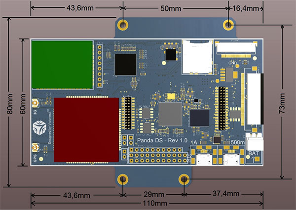
Visionect 13.3”/ 9.7” System Board mechanical schematics
- PCB: Components placed on both sides of PCB, PCB thickness 1.55mm
- Tallest top component: 5.00mm
- Tallest bottom component: 1.85mm
Visionect 32” System Board
The Visionect 32” System Board is used to drive the 32” grayscale and color E Ink electronic paper displays, as well as a combination of up to four E Ink screens (4x9.7” or 4x13.3”). The Board comes with support for Ethernet, 3G and WiFi. It can be used to connect additional peripherals, such as external LED, ambient light sensor, low-temperature heater and others.
The Visionect 32” System Boards differ in functionality between revisions, as we gradually add new features to the display driver boards.
| Revision | Connectivity | Changes |
|---|---|---|
| 0.1 - 0.4 | Ethernet | |
| 0.5 - 1.0 | Ethernet, Wi-Fi, 3G | New connectivity options, new connectors for peripherals, changed board dimensions to accomodate new 32’’ E Ink display layout. |
| 1.1 - 2.0 | Ethernet, Wi-Fi, 3G | 42’’ display support, new dpu, epson current leakage fix and minor hardware improvements |
Display support
The 32” System Board can be used to drive the 32” E Ink display (both grayscale and color are supported) or up to four 9.7” or 13.3” displays driven simultaneously. The 32” E Ink panel connects to the board via 4 FFC cables, while the 9.7” or 13.3” displays require a flat flexible cable (FFC) and a custom display interconnect adapter provided by Visionect.
Setting VCOM
Every electronic paper display comes with a VCOM label. The VCOM setting is unique for each screen and controls the baseline for the white and black colors. Because of that, a wrong setting might reduce image contrast.
Warning
The wrong VCOM setting can lead to unexpected display damage and/or reduce its lifespan!
If you are using our 32” development kit, the VCOM has already been set by us. If not, you can set it yourself.
To set the VCOM, use the VCOM configurator and a screwdriver. You should configure it so that the measured VCOM voltage (between the measuring point and ground) is in line with what is printed on the display (label).
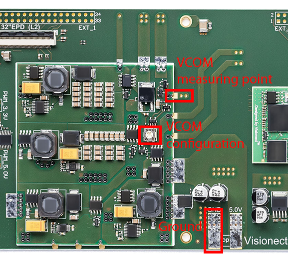
Setting VCOM
Communication
The 32” System Board comes with Wi-Fi, cellular (2G/3G) and Ethernet connectivity. Only one type of connectivity can be active at one time.
Visionect 32” System Boards version 0.5 and higher support Wi-Fi and cellular connectivity, while older versions support Ethernet only.
Ethernet connectivity
Standard 10BaseT/100BaseTX Ethernet, Auto negotiation (Full/Half duplex, 10/100 based). IP fragmentation is not supported. Multiple connector options - RJ45 jack, low profile JST connector or flying-lead soldering.
Cellular connectivity
The 32” System Board uses standards-based certified 2G/3G modules with a slot for a Micro SIM card, located on the back side of the board. The configuration of various APN settings (network-dependant) can be done manually. The integrated 2G/3G module supports Quad 2G, while supported 3G bands differ between three 3G module variants and are determined by regional/carrier compatibility. The bands need to be confirmed prior to ordering, so please send your target network/area with your order.
To use 2G/3G connectivity mode, an activated SIM card is necessary, as well as a 3G antenna (connected to 3G connector of the Visionect System Board).
Note
The Micro SIM connector is located on the front of the 32” System Board, between the RJ45 jack and the MicroSD connector.
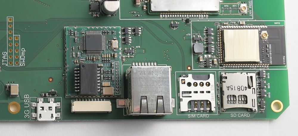
32” system board SIM slot
Note
The Micro-USB connector labeled 3G USB serves as a data port for the mounted SIMCom module and is used for flashing the module’s firmware. For serial port communication, please use the other Micro USB connector labeled ‘USB’.
Wi-Fi connectivity
Visionect 13.3” and 9.7” System Boards use standards-based certified IEEE 802.11 B/G/N modules with WPA2-PSK encryption. The modules are configured to use WMM-Power Save features on access points that support the functionality.
The Wi-Fi network quality will critically determine performance and stability. Every device relies on good Wi-Fi connectivity, so a noisy environment with a lot of clients running on low quality access points will cause problems.
The quality and configuration of the Wi-Fi access points also plays an important role when determining battery life and the device autonomy of a device in standby, but still connected. Find out more about power consumption, battery life and optimizations here.
Power options
The Visionect 32” System Boards are powered directly with a 6A 5V regulated power supply. If you plan on driving external LEDs, please add that to the required power budget.
Warning
Using a low quality or inappropriate power supply will cause System Board erratic operation, noticeable in a degraded image quality and general Board instability.
For battery and/or solar cell operation, external batteries with the proper voltage output are required. The Visionect 32” System Board allows for the monitoring of the external battery voltage, reporting this data back to the Visionect Software Suite.
External Peripherals
Extension list
Note
The following extension list is for revision 0.6 and greater. For older devices, please check the description under DATA_Connector pin.
| DATA_Connector pin | Extension board pin | Function (from MCU) | Description |
|---|---|---|---|
| 1 | SCL | I2C SCL | LED PWM controller NCP5623 I2C SCL |
| 2 | SDA | I2C SDA | LED PWM controller NCP5623 I2C SDA |
| 7 | USART1_TX | Serial TX | Text2speech module RX pin |
| 8 | USART1_TX | Serial TX | Text2speech module TX pin |
| 10 | UART RTS | Digital output TTL (0=ON, 1=OFF) | Text2speech module power enable |
| 11 | External battery | Analog input (x0.6594) (0-3.3V) | Battery monitor voltage |
| 12 | LDR | Analog input | LDR resistor divider voltage |
| 31 (15 on rev. 0.3) | External battery EN | Digital output TTL (1=ON, 0=OFF) | Battery monitor supply control |
| 13 | HEATER_ON | Digital output TTL (1=ON, 0=OFF) | Heater control |
| 14 | SLEEP_STATUS | Digital output TTL (1=sleep, 0=awake) | vPlatform sleep status |
| 15 (18 on Quad rev 0.3) | Standby switch | Digital input (5V tolerant) (0=ON, 1=OFF) | Standby switch (no support yet) |
| 17 (N/A on Quad rev 0.3) | VI_MEAS_ON | Digital output TTL (0=ON, 1=OFF) | V/I measurement circuit supply enable |
| 18 (N/A on Quad rev 0.3) | SENSOR_IN | Analog input | User sensor voltage (must be within 0 - 3.3V range! |
| 19 (23 on rev. 0.3) | Button 0 | Digital input (5V tolerant TTL) | General purpose button |
| 20 | AMBILIGHT_OFF | Digital output TTL (0=ON, 1=OFF) | Ambilight supply status |
| 21 | LED button | Digital Input (5V tolerant TTL) (1=ON, 0=OFF) | Button for enabling LED brightness control |
| 23 (N/A on Quad rev 0.3) | SENSOR_EN | Digital output TTL (1=ON, 0=OFF) | User sensor enable signal |
| 24 (25 on rev. 0.3) | Button 1 | Digital input (5V tolerant TTL) | General purpose button |
| 25 (26 on rev. 0.3) | Button 2 | Digital input (5V tolerant TTL) | General purpose button |
| 26 (31 on rev. 0.3) | Button 3 | Digital input (5V tolerant TTL) | General purpose button |
| 27 (also on rev. 0.3) | 3V3 | 3.3V | |
| 28 | 3V3 | 3.3V | |
| 29 (also on rev. 0.3) | GND | GND | |
| 33 | GND | GND | |
| 34 | 3V3 | 3.3V |
To configure the device, check the configuration section.
Display interconnect extension
With the use of display interconnect extensions, it is possible to connect up to 4 x 9.7” or 13.3” panels.
Front-light LED & ambient light sensor
Visionect 32” System Board comes integrated with a front-light LED lighting solution that can be used to add light to the display during night. The display driver uses PWM to drive the LEDs (max. 20W power). If you require more there is also an additional PWM output signal which can be used to drive an external LED lighting solution.
There are 31 discrete brightness steps that can be dynamically configured by setting the output value from the application via the Visionect Software Suite (using Javascript) or using the integrated ambient light sensor to dynamically react to ambient light. Using the ambient light sensor is fully automatic (no integration with your app required). The configuration is set using a translation table and filtering which can configure the speed of the reactions to your specific use case.
External heater
To accommodate operation at very low temperatures, it is possible to add an additional heating element that is controlled by the System Board The temperature measured by the board is used to toggle the external heater via a 3.3V output pin on the I/O header. The operation (on/off temperature and hysteresis) is configured using the CLI or remote device configuration.
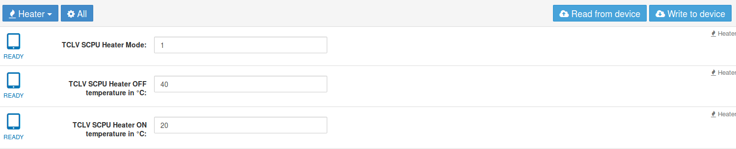
Example of setting a heater (on: 20°C, off 40°C)
External battery monitor
Since the Visionect 32” System Board not include support for Lithium Polymer batteries like the 13.3” and 9.7” Boards , a solution is provided that can monitor an external battery connected to the Board. As different batteries behave differently (different discharge characteristics) we report the external battery voltage in mV. The conversion from mV to % can be performed by end user application - mV data is available in the device session or via the Visionect Software Suite API.
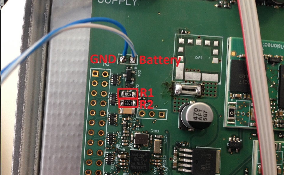
Connecting an external battery to the 32” System Board, revision 0.5-1.0.
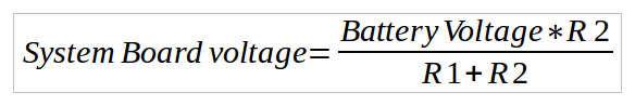
System Board voltage formula
Warning
Battery monitor uses internal ADC which means you need to provide 0-3.3V or you risk permanent damage to the driver board. You can use a simple voltage divider (calculate values, so the output of the voltage divider (R1-R2 on the image) is a maximum of 3.3V).
To check the external battery value for your driver, go to default “Settings” on the Management Interface of the Visionect Software Suite, select the checkbox of the External Battery feature and save the settings. The external battery values should then be displayed in the Devices sub-menu.
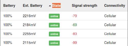
External battery values in the Admin User GUI
External buttons
Visionect System Board 32” has support for external buttons. For use in applications please check button push event section. Before use check external button extension scheme below.
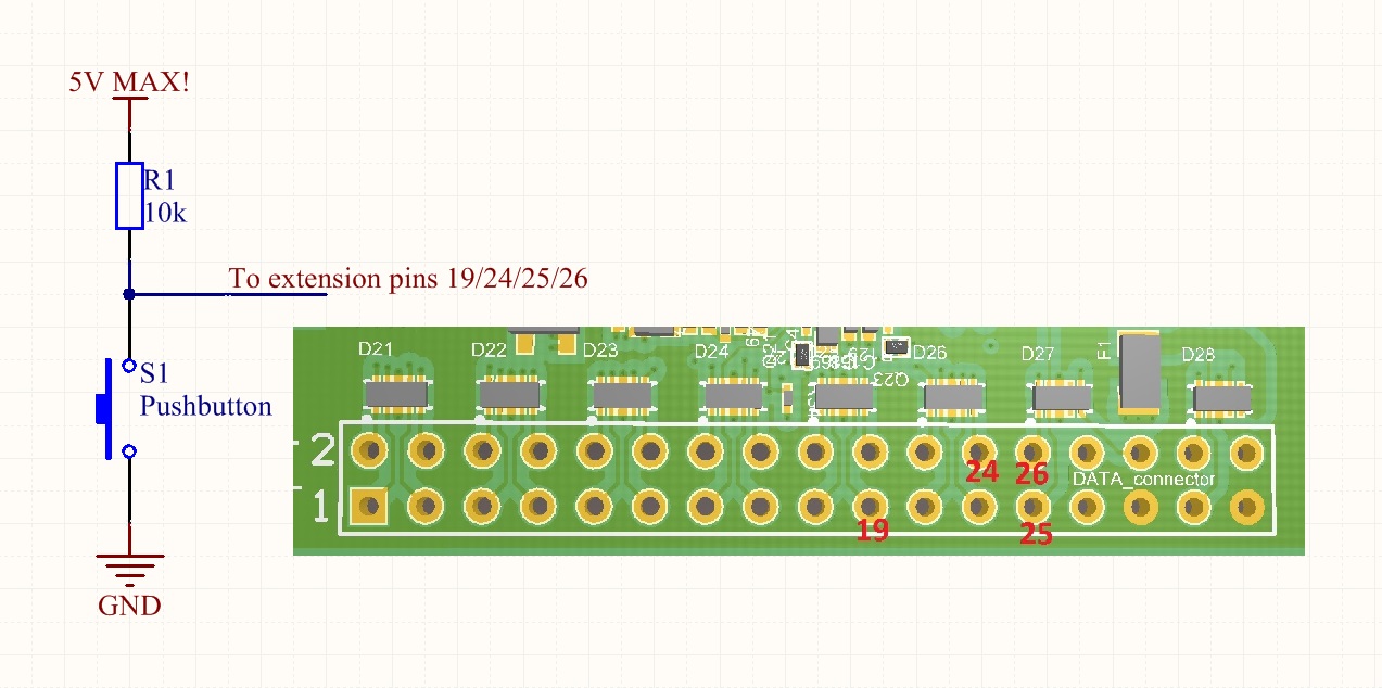
External button extension scheme
To enable the button support, type following commands:
# Read the current configuration for the SCPU
scpu_config_get
# Enable the buttong with command. If you use the function to disable the front light when the
# battery is under the threshold you need to change the parameter to 0x5
scpu_dev_mode 0x4 /
# Send the configuration to the SCPU
scpu_config_set
# Save the configuration in the SCPU EEPROM
scpu_config_save
# Reboot SCPU
scpu_power 0
scpu_power 1
| Mode | Pin number |
|---|---|
| Ground | 29,33 |
| Power | 27,28,34 |
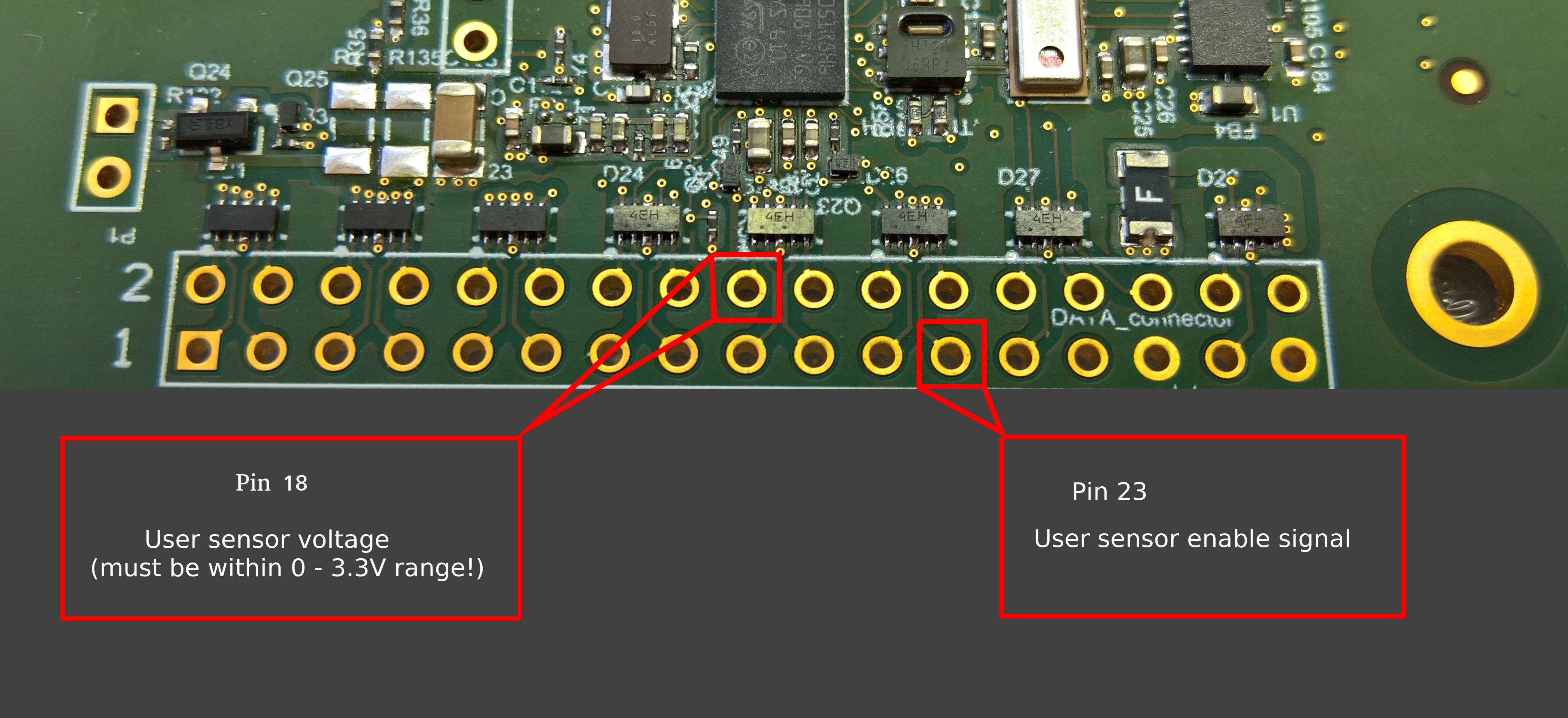
Analog input measurement (ADC)
Note
ADC measurement is supported in Software Suite 4.0 and firmware version 3.7.1622 and newer.
Analog input measurement is used to measure arbitrary 0-3v3 input. The input “SENSOR_IN” is converted into digital value (0-3300) and can be read out in the device status (via API or Javascript Javascript). To further optimize power consumption it is possible to use the measurement trigger (“SENSOR_IN”), which triggers as the board is measuring the value. Pin layout for ADC measurement, check extension list for more informations.
Configuring Visionect 32” driver
Like the Visionect 13.3”/ 9.7” System Board, the 32” Board is configured via using the provided Micro USB configuration cable and the Visionect Configurator.
The one big difference is the Micro USB configuration cable itself. While the 13.3” and 9.7” Boards require a special configuration cable provided with each Board, the 32” Board comes with the FTDI chip already integrated, which means a normal Micro USB cable can be used.
Apart from this, the instructions are the same. Connect the configuration cable to the Micro USB port on the System Board and use the Configurator to configure the network and other device parameters.
Specification - rev. 0.5-1.0
| Parameter | Specifications | Unit |
|---|---|---|
| Display |
|
|
| Wi-Fi Connectivity | 2.4GHz IEEE 802.11 B/G/N standard, WPA2-PSK support. | |
| Ethernet Connectivity |
|
|
| Cellular connectivity |
|
|
| Power supply |
|
|
| Dimensions | Size (H/W): 400 x 100 | mm |
| Weight | 240 | g |
| Operational temperature range | 0 to +50 / 32 to 122 (For the optimal display performance, the temperature sensor must be mounted directly to the backside of the screen in order to measure its temperature and use the correct waveform.) | °C / °F |
| Storage temperature range | -25 to +70 / -13 to 158 | °C / °F |
| Front-light option |
|
Schematics - rev. 0.5-1.0
32” quad driver (rev. 0.5-1.0) mechanical schematics
- PCB: 1.60mm
- Tallest component: 13mm
There are on-board positions to connect:
- Power supply
- Front-light
- Ethernet
- Temperature Sensors (pluggable)
- Ambilight Sensor (pluggable)
- 3G antenna
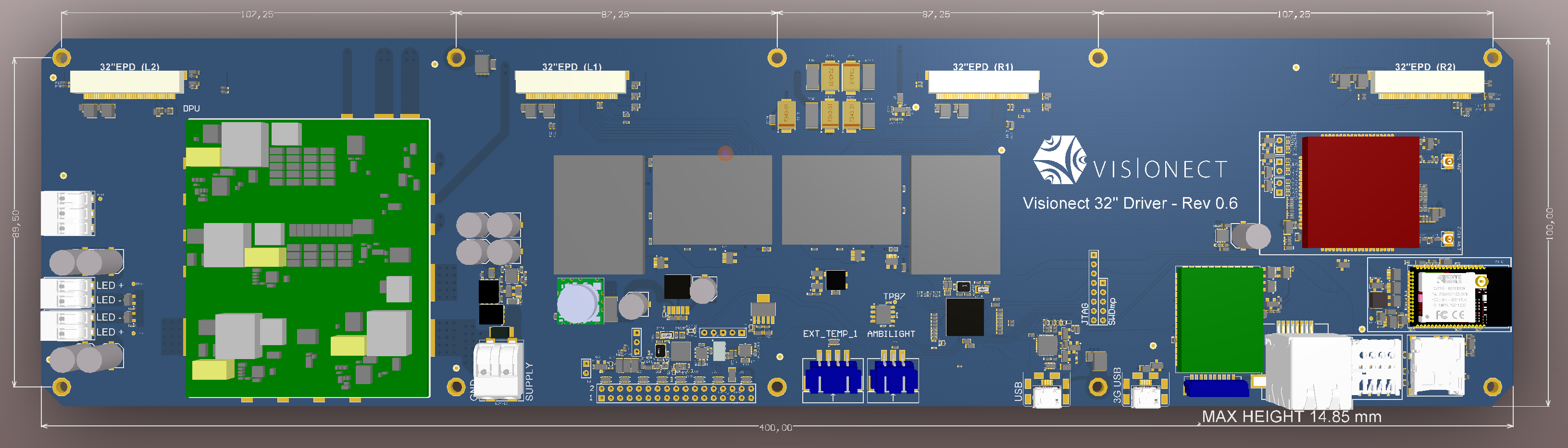
Layout overview
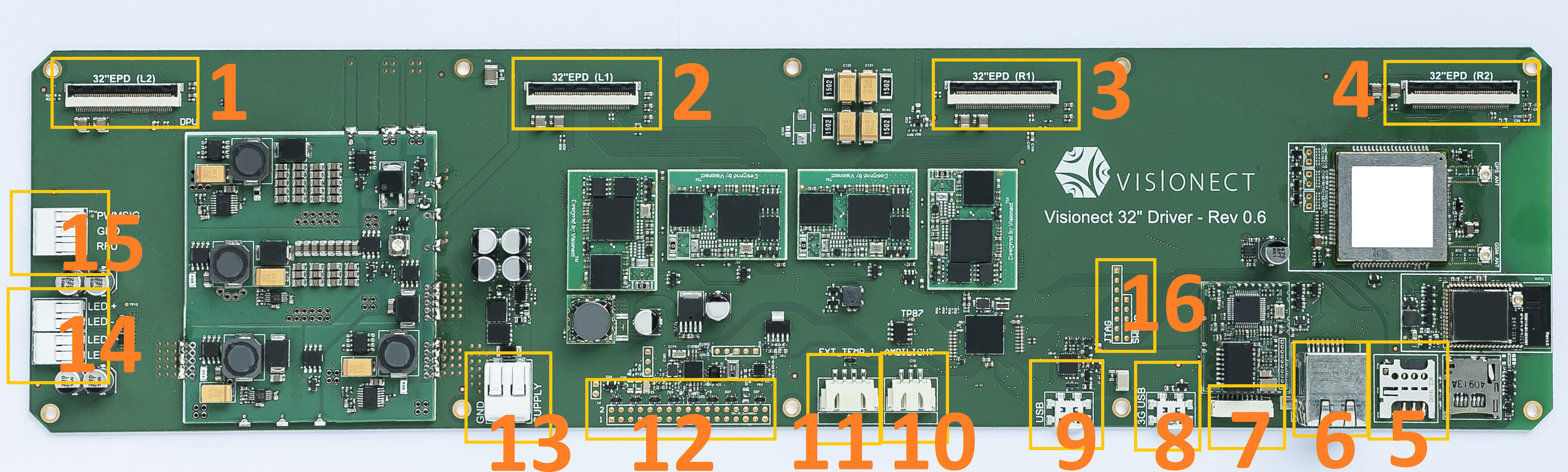
32” quad driver (rev. 0.6) Connectors explained
LEGEND:
- 1-4: EPD display connectors
- 5: Micro SIM card slot
- 6: Ethernet connector - RJ45 female
- 7: Ethernet connector - low profile JST SM10B-GHS-TB
- 8: micro-USB port - 3G
- 9: micro-USB port - serial port
- 10: Ambilight sensor connectors
- 11: External temperature sensor
- 12: GPIO (data) connector
- 13: Power connector (GND, +5V)
- 14: LED Front-light connectors - WAGO 2060 serie
- 15: PWM - WAGO 2060 serie
- 16: JTAG connector
Specification - rev. 0.1-0.4
| Parameter | Specifications | Unit |
|---|---|---|
| Display |
|
|
| Ethernet Connectivity |
|
|
| Power supply |
|
|
| Dimensions | Size (H/W): 360 x 100 | mm |
| Weight | 190 | g |
| Operational temperature range | 0 to +50 / 32 to 122 (For the optimal display performance, the temperature sensor must be mounted directly to the backside of the screen in order to measure its temperature and use the correct waveform.) | °C / °F |
| Storage temperature range | -25 to +70 / -13 to 158 | °C / °F |
| Front-light option |
|
Schematics - rev. 0.1-0.4
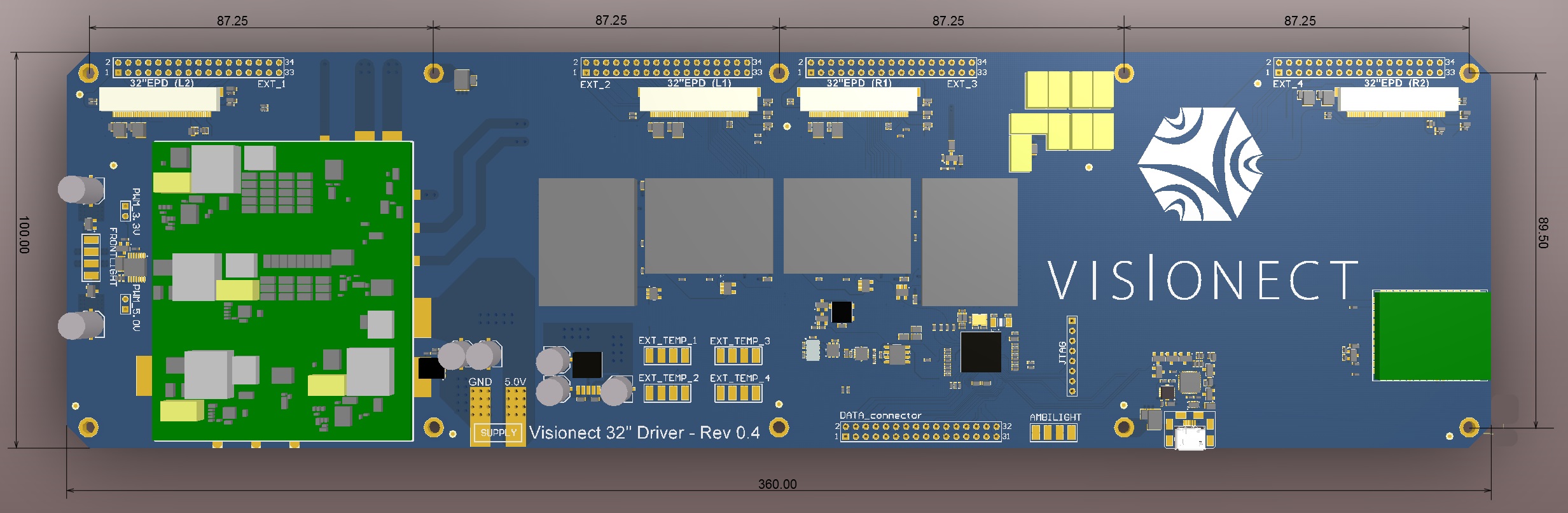
32” quad driver (rev. 0.1-0.4) mechanical schematics
- PCB: thickness 1.60mm
- Tallest component: 8.3mm
There are onboard positions to connect:
- Power supply
- Front-light
- Ethernet
- Temperature Sensors
- Ambilight sensor
Layout overview - rev. 0.1-0.4
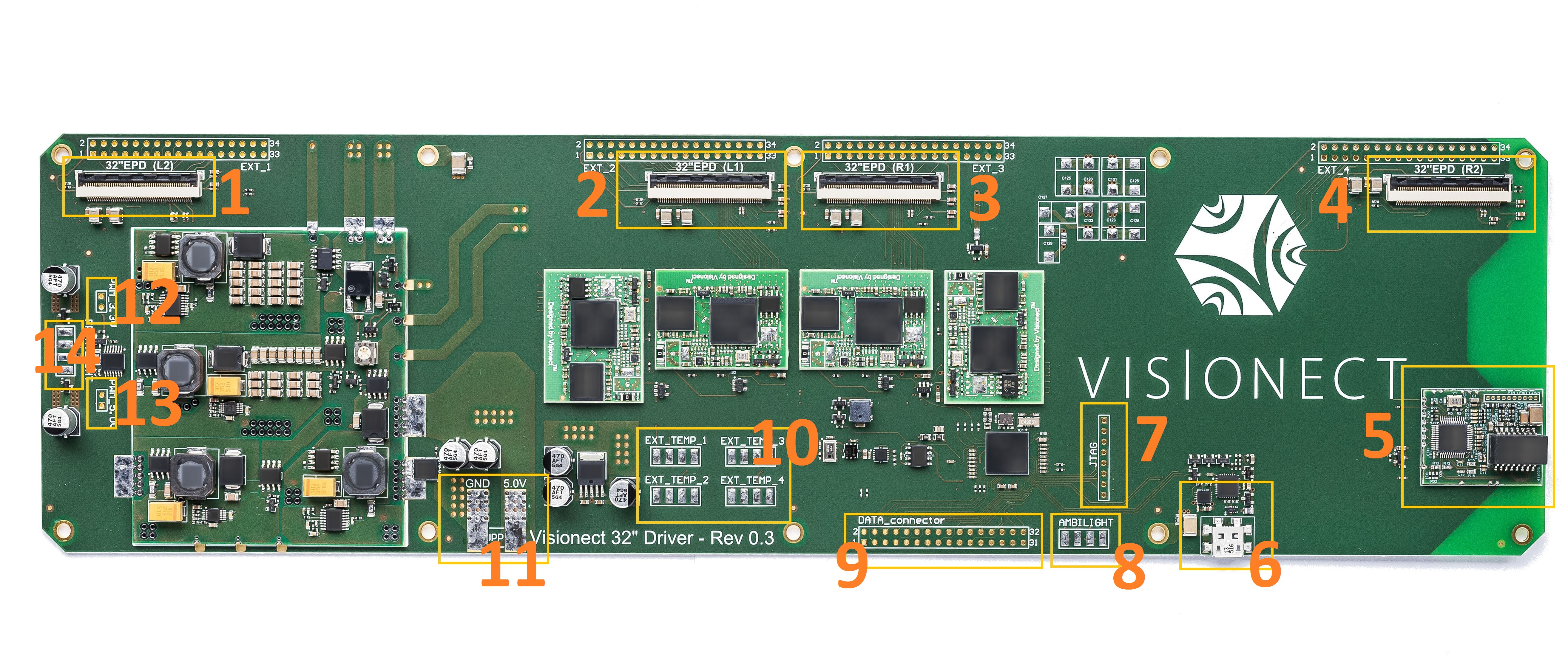
32” quad driver (rev. 0.1-0.4) Connectors explained
LEGEND:
- 1-4: display connectors
- 5: Ethernet connector
#Ethernet pinout: 1 to 8:
- 1: orange-white/TD+
- 2: orange/TD-
- 3: blue-white)/RX+
- 4: blue/NC1
- 5: green-white/NC2
- 6: green/RX-
- 7: brown-white/NC3
- 8: brown/NC4
- 6: micro-USB port
- 7: JTAG connector
- 8: Ambilight connector
- 9: GPIO (data) connector
- 10: External temperature sensor connectors
- 11: Power connector (GND, +5V)
- 12: PWM 3.3V connector (ext)
- 13: PWM 5V connector (ext)
- 14: LED Front-light connector (+5V)
Mounting & assembling
Warning
When mounting a Visionect System Board directly onto a metallic baseplate (without spacers), you should use a thin layer of isolation to make sure that the exposed contacts on the bottom side of the Board are not touching the metallic baseplate. Only mounting holes can be (and should be) connected to the metallic baseplate, if used. In case of using spacers, no other isolation is required.
LED Front-light
A LED strip can be connected either directly to the Front-light connector (+5V supply) or (when using external driving) PWM connectors (3.3V or 5V for versions below 0.5 and 3.3V for versions above 0.5).
To assure light uniformity, all LEDs need to have the same distance from the plexiglass. Also, they should not heat up the electronic paper display on the sides, as this temperature offset will impact graphical performance. Temperature variations can cause image quality issues.
Protecting the display
Optical bonding is an important part of display setup. Without protection, your display visibility will be highly reduced. As electronic paper displays have no backlight, going without optical bonding could reduce the contrast by 30% or more. For outdoor installations you might also require a front strengthened and UV resistant glass for protection against scratches and UV rays.
Warning
Exposure to UV will permanently damage your electronic paper display in very short period. Make sure you’re using glass with UV protection when deploying outdoors. If you’re planning to bond, then please make sure that the bonding material is not cured with UV. For the optimal display performance, the temperature sensor must be mounted directly to the backside of the screen in order to measure its temperature and use the correct waveform.
Mounting the display
The display connection flexible tails are covered with electronic components that will short-circuit when mounted against a conductor. Please make sure you protect the tails, as improper mounting is the most common reason why displays fail in a production setting.